STS4DNF60L Overview
The STS4DNF60L is a dual N-channel power MOSFET manufactured using STMicroelectronics' unique STripFETTM process. Based on a single-feature-size strip-based structure, this technology achieves high cell density to reduce on-resistance and improve overall device performance.
In addition, the STS4DNF60L offers rugged avalanche characteristics, allowing it to withstand transient overvoltage stress under specified conditions. It is suitable for power switching applications such as motor drives, DC-DC converters, and battery management systems.
STS4DNF60L Internal Structure
The STS4DNF60L is a dual N-channel power MOSFET that integrates two independent MOSFETs. Each MOSFET includes three main terminals: Gate, Drain, and Source, as well as an internal body diode.
1. N-Channel MOSFET Structure
An N-channel MOSFET controls the conductive channel between the Drain and Source through gate voltage. When a sufficient positive voltage is applied between Gate and Source, the channel forms and the MOSFET turns on. Reducing the gate voltage turns the device off.
2. Body Diode
The body diode is an inherent parasitic diode inside a MOSFET. In an N-channel MOSFET, its anode is connected to the Source and its cathode to the Drain. It provides a path for reverse current generated by inductive loads.
3. Impact on Switching Performance
The internal structure affects the MOSFET's switching speed and power losses:
l Gate Capacitance: Affects gate charging and discharging speed.
l On-Resistance: Determines conduction losses.
l Body Diode: Affects freewheeling capability and reverse recovery losses.
l Parasitic Capacitance: Influences switching behavior and overall efficiency.
STS4DNF60L Specifications
This section lists the key specifications of the STS4DNF60L MOSFET.
Parameter | Value |
Part Number | STS4DNF60L |
Manufacturer | STMicroelectronics |
Description | MOSFET 2N-CH 60V 4A 8-SOIC |
Lead Free Status / RoHS Status | Lead free / RoHS Compliant |
FET Type | 2 N-Channel (Dual) |
FET Feature | Logic Level Gate |
Series | STripFET™ |
Vgs(th) (Max) @ Id | 2.5V @ 250µA |
Current - Continuous Drain (Id) @ 25°C | 4A |
Drain to Source Voltage (Vdss) | 60V |
Power - Max | 2W |
Rds On (Max) @ Id, Vgs | 55 mOhm @ 2A, 10V |
Input Capacitance (Ciss) (Max) @ Vds | 1030pF @ 25V |
Gate Charge (Qg) (Max) @ Vgs | 15nC @ 4.5V |
Packaging | Digi-Reel® |
Operating Temperature | -55°C ~ 150°C (TJ) |
Supplier Device Package | 8-SO |
Package / Case | 8-SOIC (0.154, 3.90mm Width) |
Base Part Number | STS4DNF60 |
STS4DNF60L Pinout Definition

Gate (G): The control terminal. Applying a suitable voltage between Gate and Source turns the MOSFET on or off.
Drain (D): The main current terminal through which current typically enters the MOSFET during normal operation.
Source (S): The other main current terminal, providing the reference voltage for Gate control.
STS4DNF60L Key Performance Advantages
The STS4DNF60L offers several key advantages in reducing system power consumption and simplifying drive circuit design:
l Logic-Level Drive: Supports full enhancement at a gate voltage of 4.5V or lower, making it suitable for direct interfacing with microcontrollers (MCUs) and logic ICs.
l Low On-Resistance (RDS(on)): Reduces conduction losses and improves overall power conversion efficiency.
l STripFET™ Technology: STMicroelectronics' proprietary high-density trench process helps reduce gate charge (Qg) and achieve fast switching performance.
STS4DNF60L Safe Operating Area (SOA)
The Safe Operating Area (SOA) curve defines the safe operating limits of a MOSFET under different voltage, current, and time conditions. The operating point must remain within the SOA curve to prevent overcurrent or overheating.
The main electrical limits of the STS4DNF60L include:
l Drain-Source Voltage (VDS): 60V maximum.
l Continuous Drain Current (ID): 4A at 25°C and 2.5A at 100°C.
l Pulsed Drain Current (IDM): 16A maximum, subject to SOA and pulse duration limits.
The SOA curve shows separate limits for continuous (DC) operation and different pulse durations. Pulsed operation allows higher current for short periods, but the actual limit depends on pulse duration, duty cycle, and thermal conditions. The 16A rating should not be treated as a continuous current rating.
How to Evaluate the SOA Curve
1. Determine the actual drain-source voltage (VDS) and drain current (ID).
2. Select the appropriate DC or pulse curve.
3. Check that the operating point falls within the SOA boundary.
4. Consider junction temperature, thermal resistance, and cooling conditions to ensure safe operation.
STS4DNF60L Test Circuits

Switching times test circuit for resistive load

Gate charge test circuit
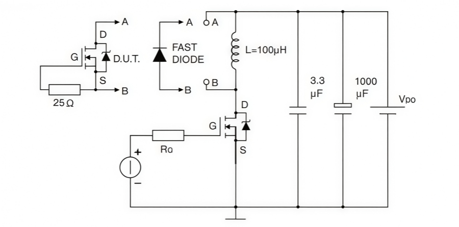
Test circuit for inductive load switching and diode recovery times

Unclamped Inductive load test circuit
STS4DNF60L Applications
The STS4DNF60L features a dual N-channel MOSFET structure, low on-resistance, and fast switching performance, so it is suitable for various power switching circuits. The following sections introduce its main applications.
1. DC Motor Drive
STS4DNF60L can be used in DC motor drive circuits to control motor current and operation by switching the MOSFETs on and off.
l DC Motor Control Circuits
l Small Motor Drive Systems
l Motor Speed Control Circuits
2. DC-DC Converters
As a switching component in power conversion circuits, STS4DNF60L controls energy transfer to convert between different voltage levels.
l Buck Converters
l Switching Power Supplies
l DC Power Regulation Circuits
3. Battery Management Systems
STS4DNF60L can be used in battery management circuits for portable devices to control battery charging and discharging paths.
l Portable Electronic Devices
l Battery Protection Circuits
l Battery Power Management Systems
STS4DNF60L Equivalents
The following five MOSFETs can be considered as potential alternatives to the STS4DNF60L:
1. SH8K32GZETB
2. FDS6982
3. DMN6070SSD
4. AP4511GM
5. STS5DNF60L
STS4DNF60L Package

ANDE Electronics: Your Trusted Partner in Electronic Component Sourcing
At ANDE Electronics, we make getting the electronic components you need simple and fast. We work directly with top global manufacturers to provide high-quality components that have passed our strict checks, so you can count on them for your projects.
We also focus on quick and consistent delivery to keep your work on schedule and avoid delays. When you need reliable and efficient electronic parts for your projects, ANDE Electronics is a partner you can trust.